Wednesday, February 21, 2024

I'm Blue, da ba dee dabba da-ee - Torch Triple X - Part 6

Time for a bit of a break from the Torch's motherboard. 

During my escapades with this computer I ended up plugging in the hard disk and floppy disk 'layer' as well as the motherboard just to check if it needed to have connection to a drive to boot (who knows with stuff this old!). Sadly, it didn't make a difference but it did show me that the hard disk actually started up and did not sound like a howling banshee. I'm looking at you, Cifer.

The main drive is a similar style to the Cifer drive and uses a stepper motor rather than coils to control the heads, as was the standard at the time. It spins up and makes some happy chirping noises. This is all a great sign but without the main computer up and running what can I do?


Hard disk, rear and centre. 
(Pic from last year before power supply shenanigans)


*BlueSCSI2 has entered the chat* (as the kids might say)

The latest iteration of the amazing BlueSCSI project now has a fantastic function called 'initiator mode'. Now, I have not been a huge follower of this project but this new feature caught my eye as it said that it could read disks even without the host computer being available. Interesting...

And by coincidence, RMC happened to mention the BlueSCSI board and how to get them from the chaps at Flamelily IT. So an order went in and a couple of days later a parcel dropped through the door.

I went for the kit version that included a configured Pi Pico which is about £14 cheaper than a fully built unit. You could order a kit without a Pico too and save another £8. Anyway, building the unit was really straightforward and basically consisted of soldering on the right angle 50 pin SCSI connector, the power connector (like a floppy drive connector) and some pin headers. It genuinely took me less than half an hour to solder everything in. If I had any complaints it was that there is literally no documentation provided with the kit but given the limited soldering needed to build it I suppose that's not a major problem.

BlueSCSI raring to go..

Documentation to use the thing is available from the BlueSCSI github and it's also linked to from the Flamelily website.

First things first, to read a disk image I need an SD card (full size). Fortunately I have an 8Gb microSD and a gazillion adaptors to convert it to full size. This card needs to have a small file on it to tell the board to go into 'initiator' mode. 

Next task. Get the jumpers in the right place. The unit in the Torch uses a standard SCSI 50 pin connector so it was as simple as plug it in to the BlueSCSI, insert the SD card, swap a couple of jumpers, apply power to the drive and the BlueSCSI and... 

...nothing.

Ooops. In my haste I had missed one of the headers on the board that had to be set for 'initiator' mode. Install the header and stick a jumper on.


Target the initiator! Or something...

Initiate! Initiate!

Take 2.

The drive spun up and the Pico light began to flash, slowly at first but then it started to flash quickly and I could hear the drive heads moving. Nice! After a few minutes the flashing on the Pico went back to being slow and there was no more activity from the drive so I powered it all down.

Now, to see if there was anything viable on the card. First I looked at the log file and I could see that the drive responded to a query from the board on ID 7. Then a long list of data copying, sector by sector. Then, to my surprise, the drive also reported it had data on ID 0 and so the BlueSCSI copied that data too. I suspected that they were actually the same and it does seem to be a bit of a bug as per Adrian's Digital Basement video (released as I wrote this - spooky).

The upshot of this is that there are two .hda files on the SD card, each just over 40mb. This is great news as it means that we now have something we could possibly archive from the drive. To verify this I went and loaded one of the images into a hex editor and, sure enough, data is clearly visible.

But then I hit a snag. I decided to try and look at the files by mounting it in Linux. It did not work. It still does not work after several days of trying. I can only assume that there is something odd about the filesystem that modern systems don't like, even though the captured file is correctly identified as a 46Mb image with filesystem FAT16. Never mind. I do at least have the .hda files that should, in theory, be useable on a BlueSCSI in HDD mode once I get this thing up and running..

But wait, I have another full size SCSI drive. Perhaps I could get an image from this one too. Let's plug it in and see shall we?


Oh dear. Of course I knew it was dead before I took the lid off otherwise I would have just killed the drive myself. But it was gone. I dismantled it to see if I could find the damaged platter. The photo is just one of several that were damaged and is the only one I could get an anywhere OK photo of. For some reason trying to take pictures of highly polished surfaces is surprisingly hard!


Ring of death.


And now, back to the motherboard... (next time).

Blue.


Thursday, February 01, 2024

Socket to 'em! - Torch Triple X - Part 5

At the end of the last installment I had managed to order a spare DMA controller for not too much from eBay. Well, it arrived and I very carefully installed it in place of the existing chip and...


DMA! DMA! DMA!


...no difference. The unit stops at the blue screen, the 68010 fails to start properly and the error beeps for 'main CPU timeout' still ring out from the monitor after 20 seconds or so.

Darnit.

And it was about this point where my replacement ATX power supply started to make worrying buzzing noises. After unplugging it as quickly as possible (and following a quick change of underwear) I put it to one side and decided to come back to it later. Fortunately, I still had my bench supply and I had received a suggestion to use said supply, current limited to about 2 amps to see if I could work out if there were any shorts on the board.

To cut a long story short, the supply went straight into current limit mode and the voltage across the board was exactly the same in every location at around 2.3v. As an experiment I tried to see what current the board would actually be pulling if the voltage on the 5v rail was actually 5v. It draws over 4amps. That's 20 watts for a relatively small bunch of chips. The technical manual suggests that the supply would be drawing a minimum of 2amps but 4amps is worrying.


That's a lot o' amps..


Next thing to try was the capacitors. There are no electrolytic caps on this board but there are about eight tantalums which could fail as short circuit. Perhaps one had failed and was causing a short to ground and the excessive current draw. But after removing them from the board they all checked OK. So then, in a slight fit of frustration (not the last) I removed EVERY 100nf bypass capacitor and checked them all. And there's eleventy billion of the little buggers. I found a bunch of about 20 or so that came out as 70-80nf instead of 100nf. These are clearly out of spec and I will replace them but they're not so far out as to cause any problems. 


Should be 100nf.

Woah! Should be 100nf..

Crikey! Should be 100nf!

Can you guess what? 
Should be 100nf...

Faulty. The lot of you!


After replacing all eleventy billion of the caps and new ones to replace the faulty ones, the result was...

No difference.

Darnit. Again.

Looking over the schematics, and thinking about the various buses in the system it's obvious that the QBUS is working as we are clearly running code from the EPROM. Based on the 'garbage' that used to appear on the screen, the video RAM also seems to be working correctly as this is where the code is loaded before the startup of the 68010. With this in mind I listed out the chips that touch the PBUS and decided to de-solder them so I could test them away from the board - this also means I could install some sockets.

There were a fair few chips in that list. Some of them I could test using my el-cheapo IC tester (but more on that later) but a big proportion were 74LS244, 245 and 373s. These aren't supported by the tester so I had to think of another way to test them.

Enter the Amiga A500+ motherboard! This uses the 74LS244 and LS373 in the data path for its RAM. They are usually the chips that take the brunt of the leaking battery on the A500+ (excluding Gary - poor Gary), and so the A500+ board I have already has them in sockets. It was a simple case of swapping one chip in at a time and checking that the A500+ board booted and didn't generate a green screen. So after a half hour of chip swapping I ended up with a pile of working 74LS244s and 74LS373s.


Ah, the Amiga. 
(Ignore the sockets - I ran out of 20pin ones...)


Next, the 74LS245s. These were a bit more involved and needed me to build a test circuit on a breadboard. Using 8 LEDs, 8 resistors and a bunch of link wires, it was possible to send 8 bits across the chip in either direction based on the level of the DIR pin and check the results using the LEDs as indicators. The upshot was a small pile of fully working 74LS245s.

We're running out of possible suspects on this board...so in the next fit of frustration I de-soldered pretty much EVERY chip from the board.

I thought I had found a problem on the board when a 74LS148 came out as 'BAD' on the chip tester. There is only one of these on the board and its an '8 to 3 priority encoder' which takes eight inputs and turns it into a 3 bit binary output based on the most significant bit on the 8 bit input. The three outputs connect to the IPL0, IPL1 and IPL2 control lines on the 68010. If I have understood correctly, the combination of these lines determines the type of interrupt received by the CPU. My theory was that the faulty chip was causing a non-maskable interrupt that the CPU could not reconcile with a system device causing the CPU timeout. So I ordered some new 74LS148s.

The first thing I did when they arrived was check them on the chip tester. Every one (there were four) came out as 'BAD'.


Oh, no it isn't!


Darnit.

This was annoying for two main reasons. Firstly, I know that the chances of all of the new chips being faulty is slim. This means that this is another case of the chip tester not being accurate. Secondly, the original 74LS148 is probably not faulty either which blows my (rather good I thought) theory out of the water (and I paid for chips I didn't need).. 

The upside of all this though, is that pretty much every chip now has a socket. This will make it much easier to change chips but does introduce a small liability of poor contacts in the sockets. And the hassle of putting them all back into the board again....


So. Many. Sockets.

So. Many. Chips.


After carefully putting every chip back where it should be (foreshadowing), I tried to start it up again. And this time, it was worse. The garbage was back on screen but was not like the previous type. This garbage scrolled down the screen and stopped. No other sign of life. 

So I embarked on a marathon of chip re-seating. Fortunately, using my epic new schematics, I managed to track the problem down to the timer chip. A firm re-seating was all that was needed. The situation improved in that the garbage was as I'd seen before i.e. a series of straight lines moving down from top to bottom followed by a smaller descending rectangle of 'different' garbage. I wasn't happy though as I wasn't getting the beeps out of the monitor to indicate that the CPU had timed out.

Hmmm.

I knew that the audio came from pin 9 on the service processor so it was time for the oscilloscope. And would you believe it..


Bip, Beep, Beep, Be...

So the sound isn't working now even though the service processor is sending out the correct signal. Not a huge problem as long as I know the service processor is still kicking up a fuss about the 68010 not starting up.

But I was still puzzled why I was getting the garbage on screen. Tracing through the video palette schematics I noticed that two chips U26 and U27 should have been a 74F257 and 74F253 respectively but, somehow, they'd been mixed up and actually had a 74LS257 and 74LS253. Interesting.. I swapped U26 and the amount of garbage was reduced. So I swapped out U27 and the garbage was gone! Yay!

But was the board still generating the expected error?

Oh yes. 


I have a habit of uploading the worlds most ridiculous videos. The first 'blip' is the 'beep' it should make when it's turned on. Then, after about twenty seconds or so, the main error beep starts and is 'short long long long', the code for main CPU timeout.

So that means, after all that effort of desoldering and testing almost every IC on the board, buying some chips I probably didn't need, soldering more sockets than any sane person ever should and carefully re-inserting all those chips, I'm basically back to where I was when I started looking at this.

One thing I haven't considered, and which I really should have by now, is if any of the traces on this board have been damaged either by the leaking battery acid from the power supply, or by my removing the chips from the board. I feel a massive spreadsheet coming on..


Saturday, January 06, 2024

Are you keeping up with the Commodore...

A little while ago - sometime in July(ish) - I happened to mention my hobby of messing about and fixing (sometimes successfully) old computers to a close family friend. They, by chance had a Commodore 64 that didn't appear to be working which they hoped I could have a look at.

Challenge accepted.

After a bit of a delay we managed to pop round to see them just after Christmas and, there waiting for me, was a box containing a Commodore 64C. Nice. We tried to make it work there and then and after managing to tune in an analogue channel on their LCD TV the familiar blue screen popped up via RF, proving that the actual machine itself was somewhat working.


C64c circa 1990ish


Having prepared for the visit I had got hold of an 8-in-1 diag and dead-test cartridge which I then dutifully inserted (after switching off) to see if there were any unseen faults lurking. Sure enough, the diagnostics seemed to be saying that the user port and serial ports were 'Bad' as was the SID (darnit).


Bad SID. But is it though?


Despite this, we persevered and tried to load a game in from tape. It didn't work. The screen went blank as expected but nothing was found on the tape.

At this point I needed to get it back home and on the bench to see what could be done to restore this C64C to its former glory. In particular, I was keen to know whether the serial and user ports were 'Bad' because they were actually faulty or whether the diagnostic was expecting some sort of test harness to be attached. So I was entrusted with the precious machine and it came home with me.

Good news first. The keyboard works perfectly. Every key is fine and is registered immediately it is pressed. Next, the SID was not dead! Yay! The SID in the C64C is the later 8580 variant which, although viewed by some as inferior to the original 6581 chip, is generally regarded as a bit more reliable and less likely to fail due to old age. The diagnostic still reported SID as faulty and because we didn't have any sound on the RF I thought that this was correct. However, when I got home I used a composite video cable with separate audio to connect to the TV and the diagnostic sound tests come through loud and clear. It isn't 100% though, and the 'burn-in' tests report one minor failure when it tests the SID. I can't work out what that is but it didn't seem to affect the games that loaded up later - but I'm getting ahead of myself. SID working is a huge relief as prices for original chips are currently sky-high and are likely to only keep climbing as more of them fail over time.


One fault on SID but it's not noticeable


Back to the faults. With the Cassette apparently not working and the serial and user ports reporting as 'Bad' I immediately suspected the CIA chips. There are two of these on the board (similar to the later Amiga) and they control various input and outputs e.g. keyboard matrix, timers etc. I opened up the C64C and it was obvious no-one had been in there previously, even though the warranty seal had been broken. Straight away I could see that the two CIA chips were soldered directly to the board.


Left keyboard support

Right keyboard support

Main board top view


CIA chip

The other CIA chip

One way to troubleshoot the CIAs is to swap them over. If the fault changes then one of the chips is faulty. To swap these I would need to de-solder them from the board. This was slightly nerve-wracking as I have never worked on a C64 board before. I've done plenty of Amiga A500s but the C64 is a much earlier computer and the earliest boards can be fragile. Fortunately, there were no issues with this board and it was actually very reminiscent of the later A500 boards, being of a pretty good quality. I took my time too and I have just replaced the nozzle on the 'moo-ing' de-solder station which also probably helped.


CIA chip removed and socket
added


With sockets installed for both chips I checked to make sure it was behaving as it had done previously, which it did, and then I swapped the two chips to see if the faults changed. 

They didn't.

Ah.

I was not expecting that. This immediately suggested that the two CIAs are actually OK. So, to see if the cassette unit was working or not I dug out a blank cassette which I had stashed for a rainy day and typed up the ubiquitous 'hello world' program in BASIC. Then I saved it to tape - which I had to Google how to as I've not used a C64 before. After re-winding the tape I reset the C64 and then tried to load my saved BASIC program. And it worked.

So, this meant that the cassette drive is fine but that for some reason, the original game tapes were not being read correctly. At this point, any veterans of the cassette era will probably be hopping up and down with a single word on their lips. Azimuth.

Very briefly, in a cassette drive there is a read/write head that should be perpendicular to the track that is present on the tape. If the head is at an angle or too high or too low, the signal being read is distorted or too quiet or missed entirely, meaning that programs will not load correctly. 

To adjust the azimuth of the head simply needs a small screwdriver to twiddle the adjustment screw that is located on one side of the head. On this cassette unit the screw had a small blob of locking compound on it. To remove this I had to dismantle the unit and, while I was there, I also cleaned the read/write and erase heads with 99% isopropyl alcohol on a cotton bud.

After carefully tweaking the screw about a half turn anti-clockwise I tried loading in 'Squash'. And would you believe it actually found 'SQUASH'. At this point I had to Google what to do next as the tape had stopped. Of course, it just needs either 'Space' or the Commodore key to be pressed to continue. There are no raster bars on the 'Squash' game. Which was annoying as I had no indication that things were proceeding as expected. And then a line of text appeared across the top of the screen with the publishers name. This was a good sign. About 45 seconds later a loading screen appeared, depicting two people in a squash court. This was another good sign. 


Is this a loading screen I see before me?


Then after about five minutes the loading screen disappeared and was replaced with the original line of text. Hmmm. This was not a good sign. Eventually the tape ran to the end and stopped. 

So I tried another tweak to the screw and gave it another try. The same happened as before right up to the loading screen disappearing. I expected the tape just to run through and stop again, but I was wrong. After another minute or so the picture of a squash court with a side panel appeared, asking me to select a 5, 3 or 1 game match. Awesome!


Squash. Who's Jonah Barrington?


The other games that I had brought home to try and make work were Postman Pat 2 and Postman Pat 3. There is a Postman Pat fan somewhere in this story... :) Anyway, I tried PP2 and this got as far as a loading screen but then the game failed to start - or at least, nothing happened and the tape reached the end. So then I tried PP3 and, again, a loading screen appeared but no game at the end, just a light grey screen.

This was still an improvement!

To cut a long story short it took quite a while to hit the 'sweet spot' with the azimuth. I connected my oscilloscope to the board of the cassette drive and I could see the digital signals being fed into the C64 which was cool. I could influence the signals by going to the extremes on the adjustment screw but it was still hit and miss as to whether any game would load.


Oscilloscope - Connected to the digital input to the C64

Eventually, I undid the adjustment screw on the head until the head didn't move any further. Then I tried to load the Squash game. This failed completely so I turned the screw one quarter to slightly tighten the adjustment and tried loading Squash. Rinse and repeat. On the fourth go I got the loading screen. On the fifth, the game loaded properly. Immediately I tried loading PP2 and was met with a fully loading game! Yay! So, then straight to PP3 and although this got to the loading screen, the game failed to start again. So I tweaked to screw another quarter turn and tried PP3 again. And it loaded, perfectly.


Postman Pat II


Postman Pat III


Then, to make sure the adjustment was still OK I went back and loaded Squash and PP2 again. And they both worked without (too much) trouble. One thing I did find was that Squash will only load from side 2 no matter how the azimuth is adjusted. Odd, but bearable providing the two PP games worked!

Finally, to make sure that the adjustment didn't move again I put a blob of Mrs Crashed's nail varnish on the screw to lock it into place. 

One final test, I loaded all three games again after re-assembling the cassette drive to make sure that I hadn't messed anything up while I was screwing the case back together. 

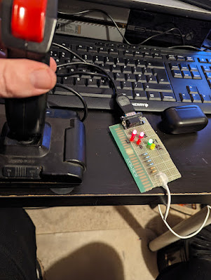
So now the main unit is working, the games load from tape and the only thing left to do was to check the joysticks. Time for my Heath-Robinson USB powered joystick tester! 


Archer Joystick under test.
Up and Right directions lit.


The first joystick is an Archer quickshot 2 clone (Archer being a brand of the now defunct Tandy - or Radio Shack if you're in the US). This is the better of the two units as it has microswitches and actually feels very sturdy. All the directions were fine and the trigger fire button was OK too, as was the 'auto-fire' function. The top fire button didn't work, and I suspected it was just the microswitch that needed a clean. Sure enough, after removing the cover from the handle and a quick clean being carried out on the top microswitch, it was back in business.


Top microswitch needed a clean.

The second joystick is a Quickshot Python. This worked without any issues although it's not as nice as the Archer as it doesn't have the nice clicky microswitches. I used to have one of these with my Amiga, back in the day, so it did bring back some happy memories. 

And that's basically it. This C64 is ready to go back and be enjoyed again by its original owner.


Wednesday, December 20, 2023

Slow and Steady... Torch Triplex - Part 4

At the end of Part 3 of this series, my ATX power supply died. It's confirmed dead. It has gone to meet its maker etc etc. Fortunately, there is a steady supply of reliable and safe second hand ATX power supplies in the form of everyone's favourite auction site.

Not really. Most used power supplies are potential hazards and should be treated with caution.

The second hand unit I acquired was particularly interesting to me as it has -5v in amongst the various voltages on its connector. This is a voltage that doesn't appear on modern PSUs but it is required for the Torch. I also checked the inside of the unit before I plugged it in - I'm not stupid.

Bulging caps

Well, that's not good.

Way off spec - new caps required!
(No sh**, Sherlock.)

A few caps needed replacement but nothing too major and I soon had a working supply to get back to working on the Torch. Yay!

After wiring up the connector the Torch sprang back into life but, for some reason (still unknown), the garbage on screen no longer appeared. Instead, I noticed after about 15 seconds a forlorn sequence of beeps started to emanate from the monitor. Curious.

Well, not really that curious since the beeps are part of the startup error checking performed by the Torch in a similar way to the PCs 'POST' (Power On Self Test) beep codes. It was quite tricky to work out the sequence but after listening for a couple of minutes it seemed to be short-long-long-long. A quick check of the Caretaker manual revealed that this means the main CPU had 'timed out' i.e. it wasn't running. 

Now the CPU in this is a 68010 and it is directly pin compatible with the 68000 as used in the Amiga. And what do I have lying around? An A500 motherboard. Unfortunately, when I took the 68010 out of the Torch main board there seemed to be a leg missing (presumed gone). It looked like it had been melted.. Oh. Poop. After a quick repair I decided to continue with my plan to try it in the A500.


The melted leg.
(Poor quality as it's a picture of the screen of my half
working microscope..)

Legs eleven! (64 actually.)

One quick swap later and I was able to prove that the CPU itself is working fine as the A500 started up and booted to the familiar Kickstart 2.04 purple screen - well, grayscale actually as I got lazy and used the composite output on the board. It also ran the Amiga Test Kit without any problems.


68010 in an A500.


It booted. Yay!

I also checked the HLT and RST lines on the CPU (and MMU and DMA controllers) and they behaved as expected on start-up i.e. held low for a second before going high.


CPU, MMU and DMA controller

It was time to break out the oscilloscope. The Torch board has two distinct buses. One is primarily for the support processor and is called the QBUS and the other is the more standard address/data bus for the 68010 and supporting chips. This is called the PBUS.

Looking over the PBUS it was obvious that the bus is basically dead. There is NO activity at all. I am very puzzled by this. What could be causing a completely dead PBUS? All of the clocks are present and correct, power is present, although the 5v line is a little low at 4.45 volts. Perhaps there is a faulty device somewhere on the bus that is causing the failure...

There is some positive news. Thanks to some help and advice from a most excellent chap on the VCF forums I now know that the garbage shown previously when I booted up was actually the EPROM loading data into the video RAM prior to the execution of code. This is normally hidden as all the colours are set to pale blue but, for some reason, my Torch had a minor issue with the colour palette. Why it now works I don't know - which I don't like but will have to put up with for now.


Garbage seen previously - not now though. Hmm..


As a side-quest I got hold of a 16k*4bit DRAM tester to make sure that the VRAM is actually ok. All eight chips test as fully working so there's no problem there.


Compact and bijou. 4-bit DRAM tester

What is supposed to happen when the machine is switched on is that the Caretaker ROM, with assistance from the service processor, loads a piece of start-up code into video memory which is then executed by the main CPU. This means that my Torch is starting correctly but, because of the apparent PBUS issues, it's failing to execute the code and get the machine fully up and running.

The problem here is that there are so many components around the PBUS. There loads of driver ICs (LS244s and LS245s) as well as various latches (LS373s) and more. And that's not even including the 68010 CPU, 68450 DMA controller or 68451 MMU. At least I know that the 68010 is OK as I've tested this in the Amiga A500 motherboard and it works fine. I've managed to order a 68450 DMA controller for not too much from eBay so I should be able to confirm if that works and it's worth having a spare if the original is OK. 

The real fly in the ointment here is the MMU. When you search on eBay and the only result for a 68451 is a VTG daughter board from a VME/10 located in the US for around £660, you know that the MMU is going to be the purest of unobtainium. 

Gah.


Sunday, October 22, 2023

A mug's eyeful.

There used to be a reason for vintage computer collectors to head to car boot sales. Tons of stuff going for pennies used to adorn the tables of the happy 'booters' (well, maybe not adorn but there used to be a fair bit). An Amiga A500+ for £3, a CD32 controller for a fiver, Commodore 64 (boxed) for a tenner etc etc.

Those days are long gone. Anyone who has anything remotely vintage either sticks it on eBay or heads to the car boots with ridiculous prices in mind. Things are so bad now that there are even Facebook groups dedicated to the delusional people of eBay and the whacky and bizarre prices that they think their stuff is worth. My favourite was a chap in Scotland who for several months put his boxed Amiga A500 on eBay for the sum of £1000 starting bid. If that had been serial number 1, signed by Jeff Porter and hand delivered by R J Mical, it might have been worth it. In reality, they're worth less than 1/10th that.

I digress. 

A few weeks ago, Crashed Jr(1) let me know of a 'PC' that was at a local fete for a very reasonable price. He sent me a picture and it turned out to be an Amstrad PCW9512. 


I know this! It's a CP/M system..

For those of you not in the UK, the Amstrad PCW9512 was one of a range of low cost PC like machines that dominated the early low-end small business computer market. I actually used one of these many, many years ago at an estate agents I worked at. It uses CP/M and has a primitive word processor and, originally, came with a printer too - no printer with this one but that's fine.

So, does it work? Well, the thing with these machines is that they are very much built to a price point so to actually get this thing up and running requires either the word processor disk or the CP/M disk. Switching on with no disk in the drive gives a beep and a white screen and nothing else. Without the disks, this is a lighter than you'd imagine paperweight.

And on the subject of disks... The more astute of you might have spotted that this thing actually uses 3 inch floppy disks rather than the more usual 3.5 inch disks. The story is that Alan Sugar managed to blag a boatload of 3 inch drives dirt cheap and so they went into every machine Amstrad generated that used floppies (CPC6128, PCW8256 etc etc). Not sure if there's any truth to that but anything's possible

Anyway, this unit did exactly as expected when I got it home, i.e. it has no disks so it just shows a white screen. I did have a 3inch disk for a PCW8256 but I didn't realise at the time they aren't compatible so when I put it in, nothing happened. But not exactly because of the incompatibility..

The floppy units in these machines use a drive belt to turn the spindle motor that makes the disk spin. And we all know what happens to rubber belts as they age. They turn into a thick, black goo that is horrible to remove from everything. To check the state of the belt I had to take the back of the machine off, then dismantle the base from the CRT so I could get the drive unit out. After taking the back off I realised I wasn't the first person to do this.. 

There are two controls on the side of the unit to control the brightness and contrast. The contrast knob had been hot glued. Oh dear. So as I took the case off, both of the potentiometers for the controls basically fell apart. Dangnabit. I managed to collect the bits and then desolder the bar that they were both attached to. 


Broken. Darnit.

After a bit of head scratching I realised that all that had happened was that the protruding control knobs were held on by plastic stakes that were melted to hold the front cover plates on. By gluing the plates back on - and trying to avoid sticking the knobs too - I could probably get away with re-installed these original ones. So that's what I did. I gave the knobs a twist to make sure they didn't stick and then let the glue overnight to cure. And the knobs were stuck solid the next day. Solved that by a firm twist with a pair of pliers. 

Fixed! Yay! Don't play with the knobs
or they may drop off.


Back to the floppy drive. The belt had, as predicted, become a sad strip of goo and needed to be replaced.


Belt has started to disintegrate

Gooey belt stuck to the main flywheel. Yuk!

In the course of moving the little green circuit board I heard a slight 'plink' of something hitting the floor. Unbeknown to me, these drives, also clearly built to a price point, have a small metal pin which drives the write protect function. This pin is not secured and simply drops into a tiny hole in the drive body. And simply drops out if you're not watching carefully..onto a small piece of patterned carpet...with the debris of many hours of soldering and other vintage computer restoration activities. 

Bugger.

Of course, at the time I didn't realise this was the case. But somewhere in the depths of my slightly confused middle-aged brain an Emergency Action Message was triggered that told me I should check the floor for something that I had never laid eyes on before. And sure enough, after half an hour of crawling around in the dust, solder blobs and occasional annoyed spider, I found it.


Dropped pin. Gah!

After checking the circuit board I located the write protect switch and made sure the pin was dropped into the correct hole. 

Back to the drive belt. After cleaning away the remains of the sticky old belt, which involved lots of scraping and cleaning with isopropyl alcohol, fitting the new belt was simple. The PCB was screwed back into place, which also then secures the write protect pin (grrr) and everything was ready to be re-assembled.


New drive belt goodness.

Controls re-installed

With the unit back together all I need now is a disk with the correct software on. I have a disk image for CP/M for PCW9512 but there are a couple of problems.

I have an additional floppy drive which is 3 inch but when I plug it into power, the drive makes 'chunk chunk' noises and the power supply (courtesy of the Cifer) goes into meltdown. A closer inspection shows that there are leaky caps just at the power connector.

Ohhh, another 3 inch drive.


It's an EME-01 (apparently)


Track damage just above the orange 
wire (mid left)

More track damage under the brown wire

Although I didn't have a full set of capacitors I did have the two values next to the power socket and a couple more on the main board. And changing them solved the problem. Bizarrely, that's the second time that changing the caps has fixed a fault and both times it was a floppy drive.

This 3 inch floppy drive is fully compatible with the Shugart standard. This means that I can use the awesome Greaseweazle with it. I managed to get a record of the disk that actually came with this drive - which was for the PCW8256 - using the Greaseweazle software with the intention of writing the the CP/M image for the PCW9512 back to that disk. 

But there are two major problems. This is only a single sided drive. The drive in the Amstrad is double sided. 

Second, the additional floppy drive only supports 40 tracks per inch whereas the PCW's drive is 80 tracks per inch. 

Arse.

Looks like I'll be heading to eBay for a CP/M disk then. Darnit.